Project 2: Mesh Editor
Ashley Nguyen | CS184-agh

Overview
In this project, I learned to build Bezier Curves and surfaces using de Casteljau's algorithm, manipulated half-edge meshes, and implemented loop subdivision! By the end of this project, I was able to load and edit basic COLLADA mesh files. This project was interesting because I was able to see how industry 3D modeling programs create smooth surfaces for object meshes.
Section I: Bezier Curves and Surfaces
In this section of the project, I work on Bezier curves and surfaces. In computer graphics, Bezier curves and surfaces are parametric curves and surfaces that are frequently used to model smooth and indefinitely scalable curves and surfaces.
A Bezier Curve
Part 1: Bezier curves with 1D de Casteljau subdivision
A Bezier curve of degree n is defined by (n + 1) control points, and is a parametric line based on a single parameter t, which ranges between 0 and 1.
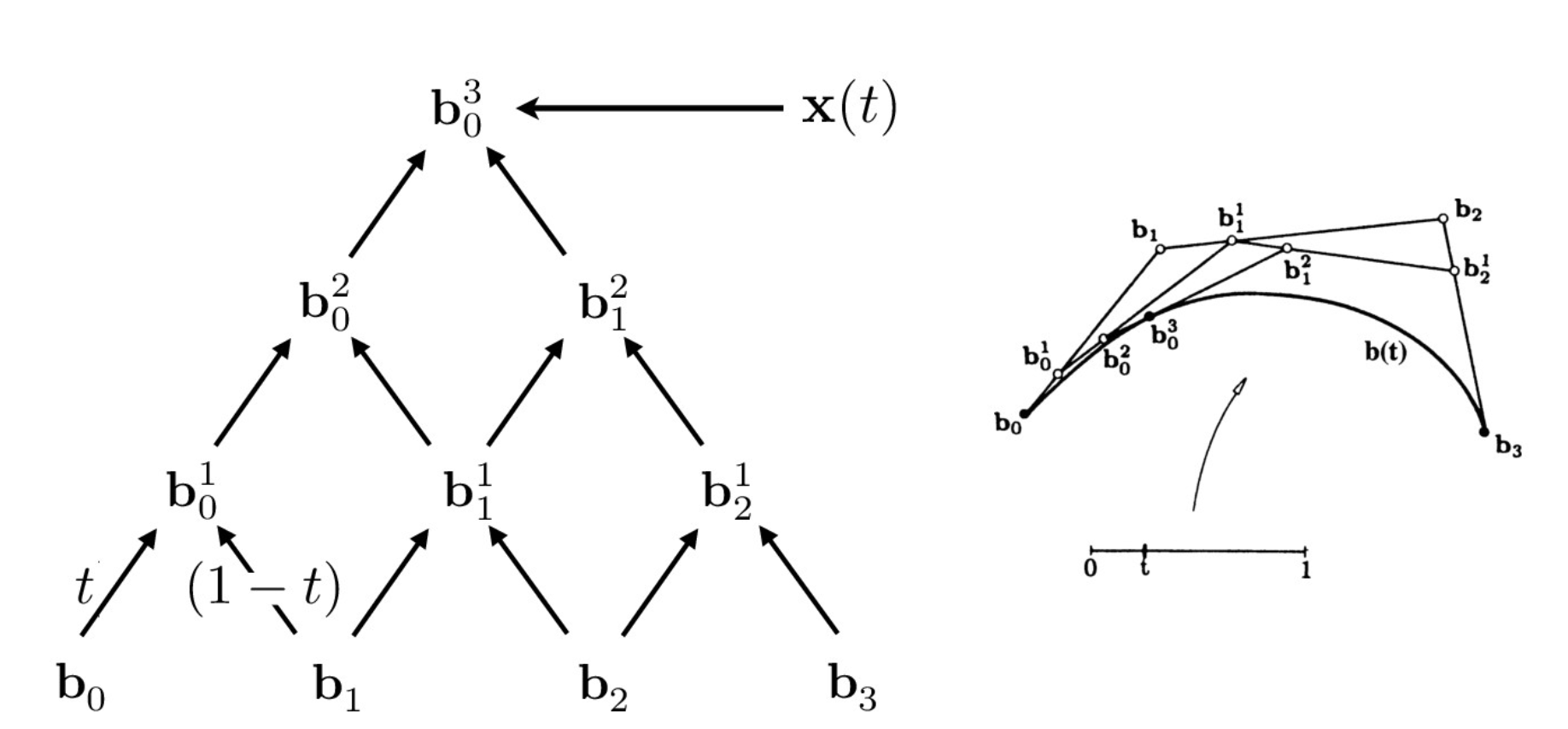
de Casteljau algorithm tree visual
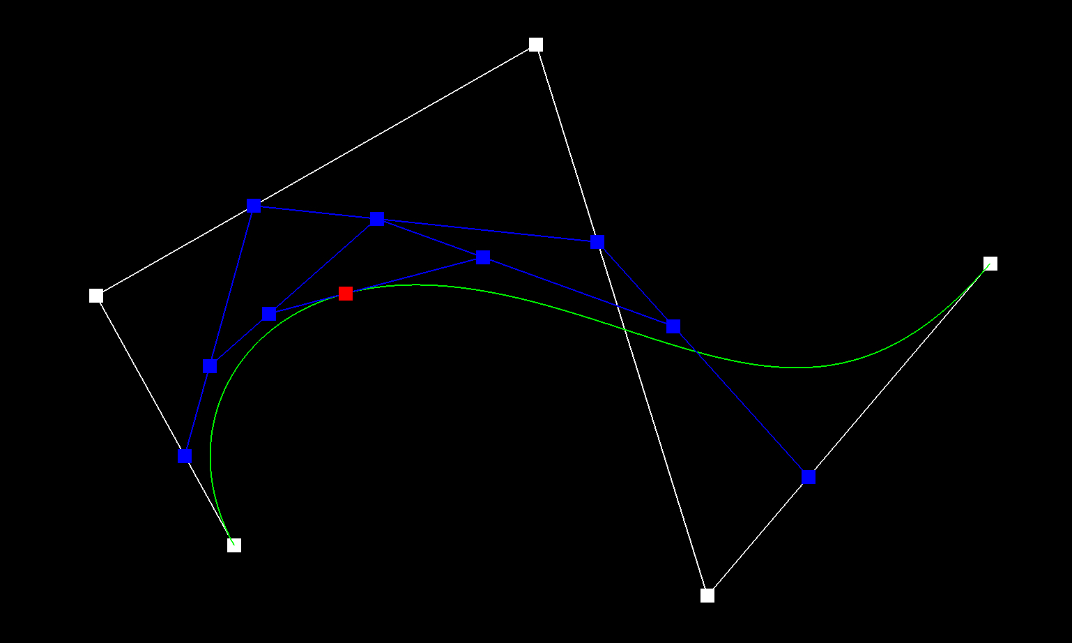
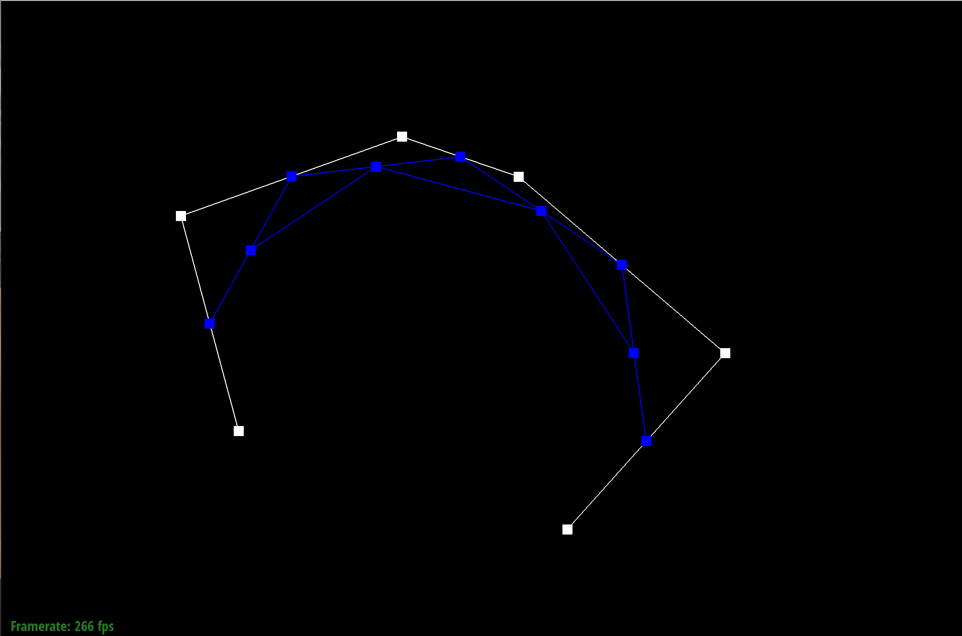
In this part of the project, I implemented de Casteljau algorithm. Using the last curve in the evaluatedLevels list, I loop through each point and calculate a point in the new level using the algorithm pt(i) * (1 - t) + pt(i + 1) * t. With this algorithm I create a new vector that has 1 less point than the previous level.
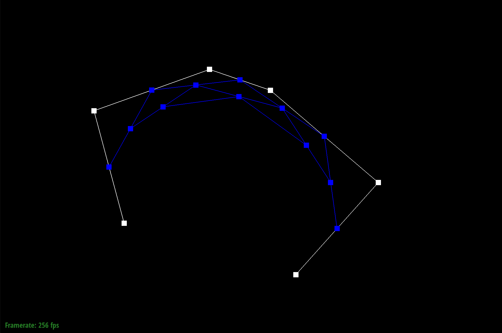
Essentially what I are doing is recursively splitting the line at some point of the line using the parameter t. After each iteration, I are able to create new control points. This loop is run until the final point is evaluated. Below you can see the process of creating the different control points. Each picture shows a new evaluated level.
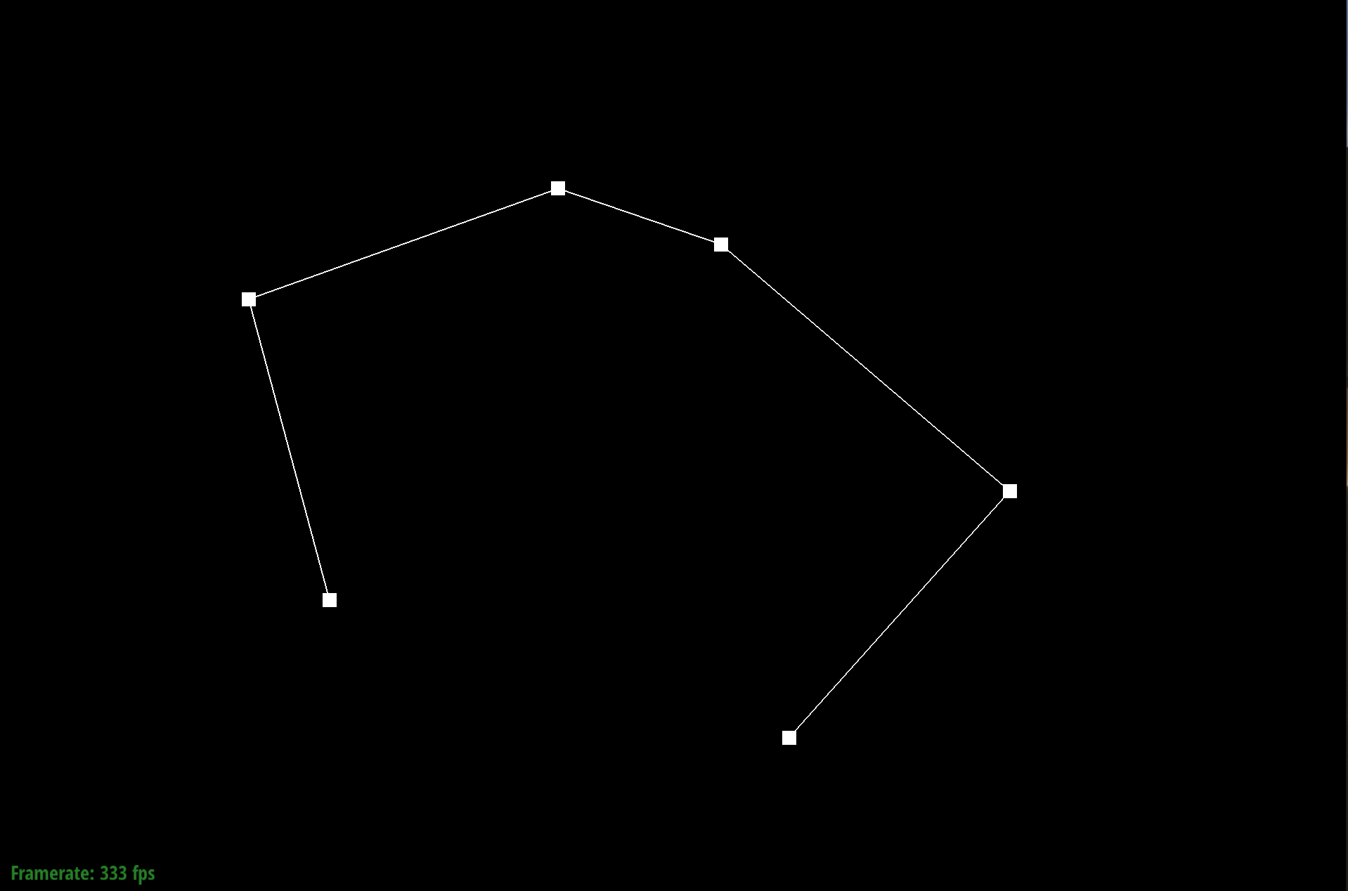
Level N
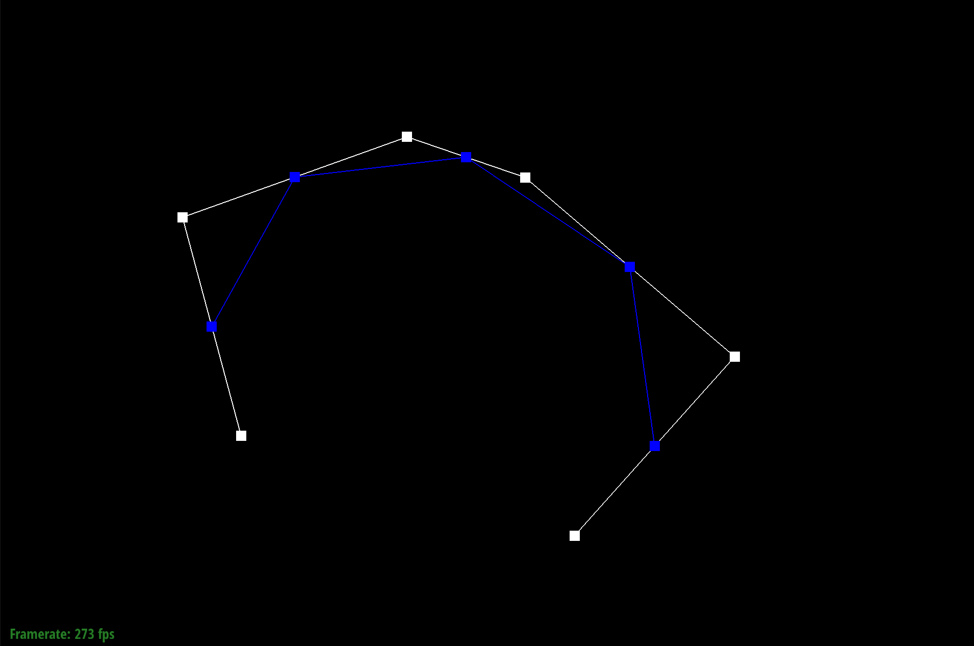
Level N-1
Level N-2
Level N-3

Level N-4
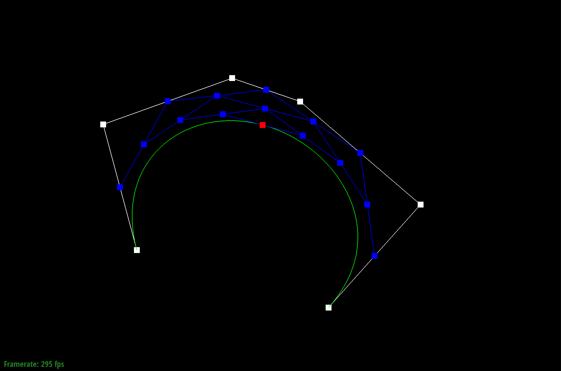
Level N-5
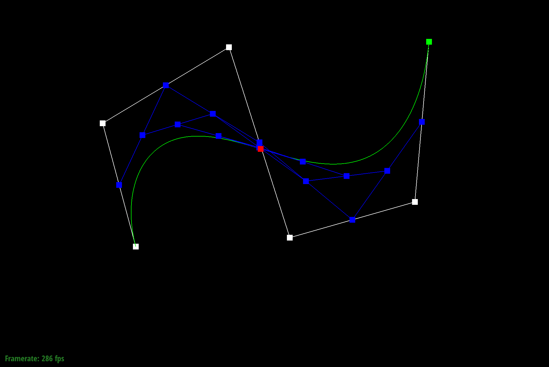
point manipulated
Part 2: Bezier surfaces with separable 1D de Casteljau subdivision
Similarly, a Bezier surface of degree (n, m) is defined by (n + 1)(m + 1) control points, and is a parametric surface based on two parameters u and v, both still ranging between 0 and 1.
Using de Casteljau's algorithm, I can evaluate these parametric curves and surfaces for any given set of parameters. In this part of the project, I use the basic Bezier curve algorithm to build Bezier surfaces. I use the separable 1D de Casteljau algorithm
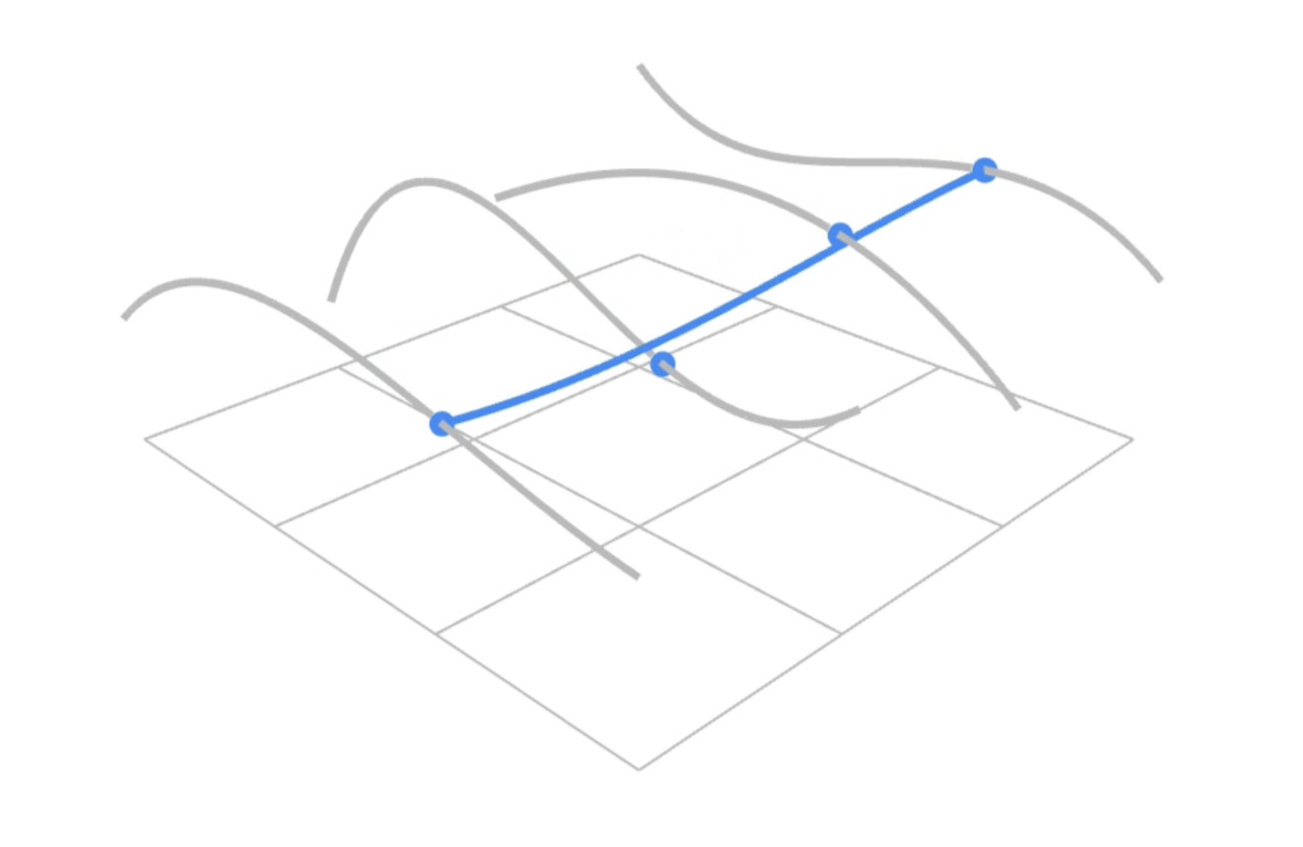
I implement this part of the project I first looping through each row. For each row I use a helper function evaluate1D that uses de Casteljau algorithm to evaluate the final point. After each row has been evaluated, I then use de Casteljau subdivision to interpolate on the final points.
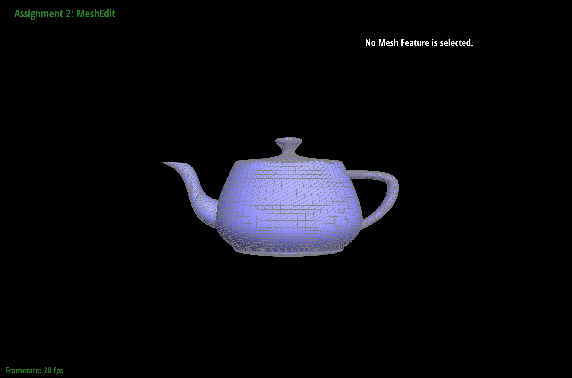
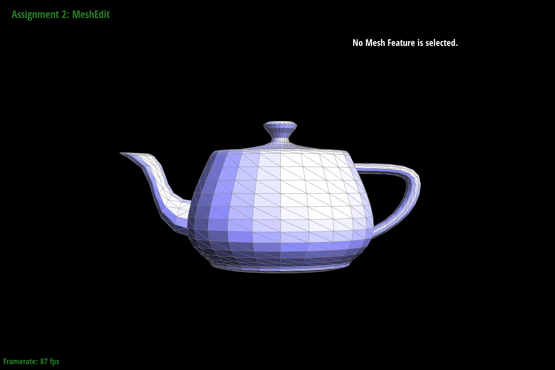
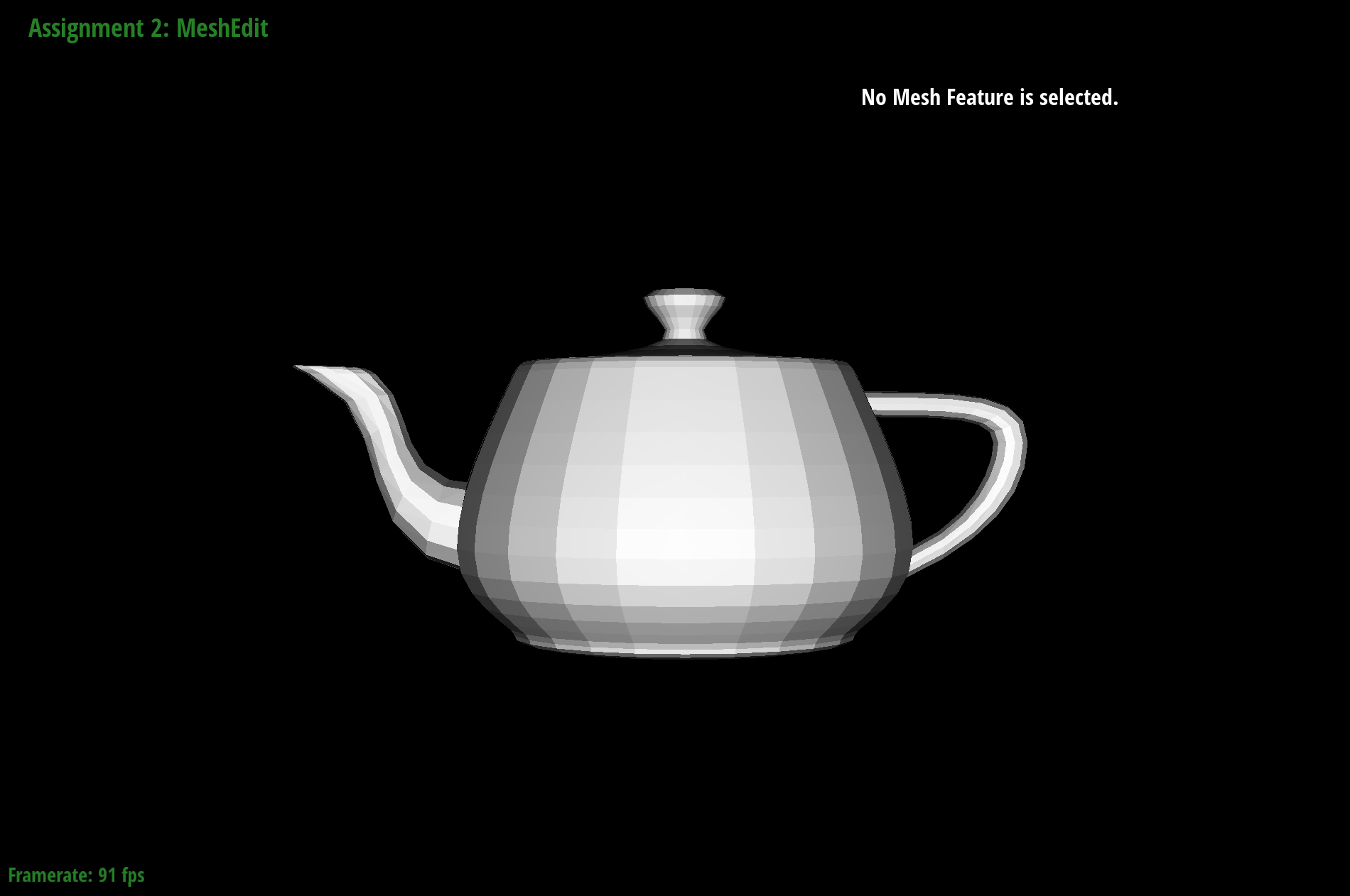
rendered teapot
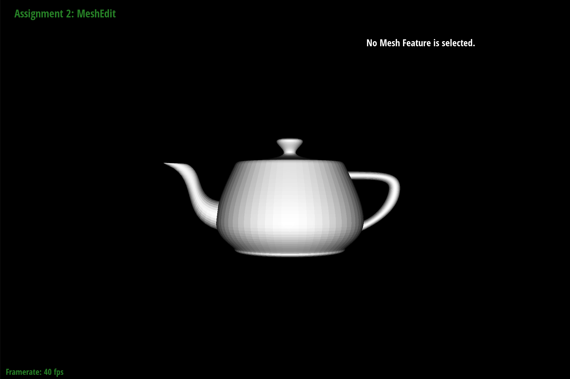
shaded teapot
Section II: Loop Subdivision of General Triangle Meshes
In this section of the project, I use triangles instead of 2D grids. Instead of being constrained by 2D grids, I are able to look at a single triangle and get access to all other triangles because they are connected by edges and vertices.
Part 3: Average normals for half-edge meshes
The goal of this part of the project is to get normal vectors at vertices to get a smoother look when shading rather than the flat surfaces. At each vertex, I loop through the outgoing edges, take the cross product of the neighboring edges. I take the sum of these area-weighted normal in a variable then normalized the unit vector. This gets us the approximation for the normal of that vertex.
Below you can see the difference between rendering with and without OpenGL. In the bottom photos the meshes are a lot more smoother than the ones on top. This helps the meshes look more realistic
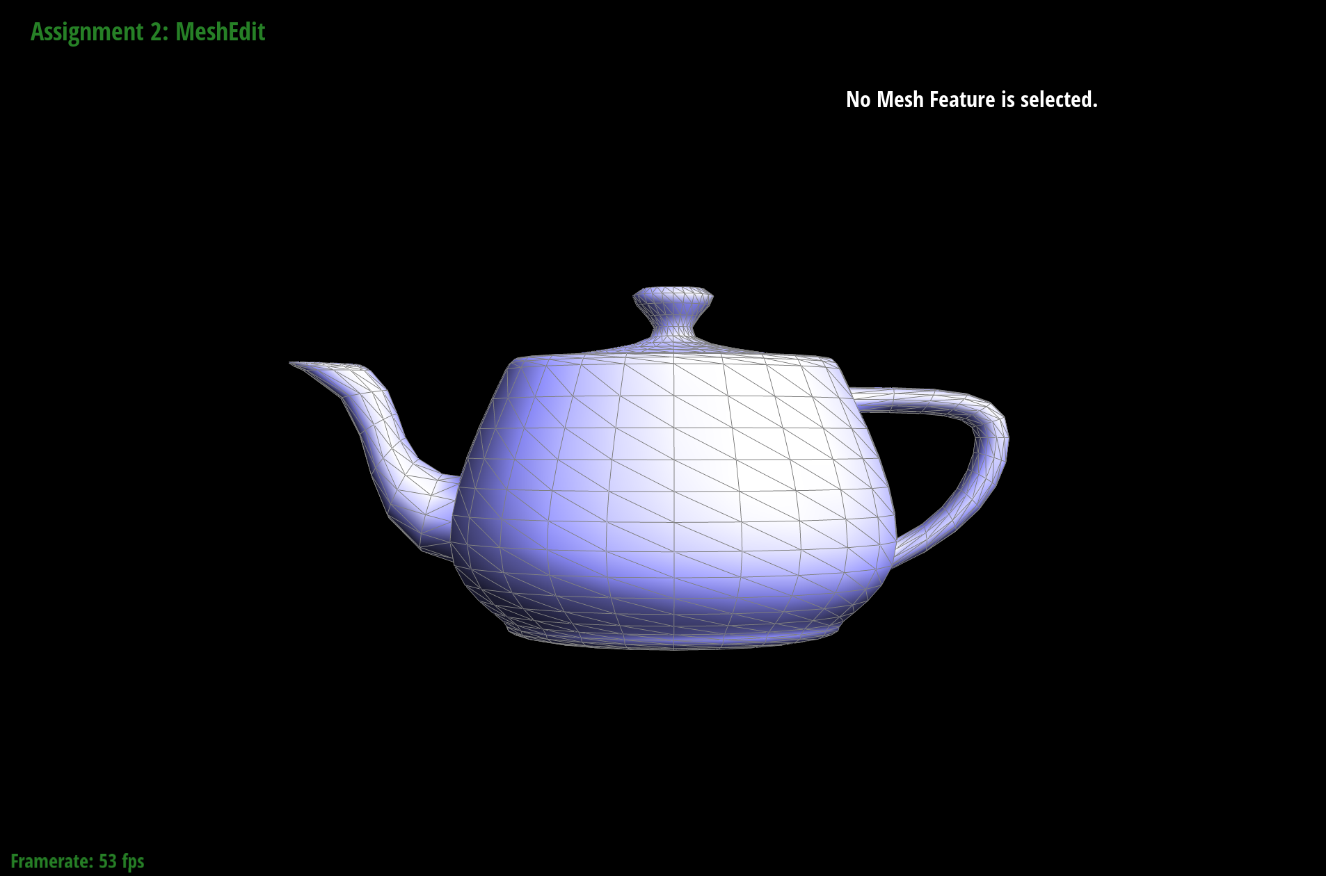
rendered
shaded rendered
rendered with smoothed edges
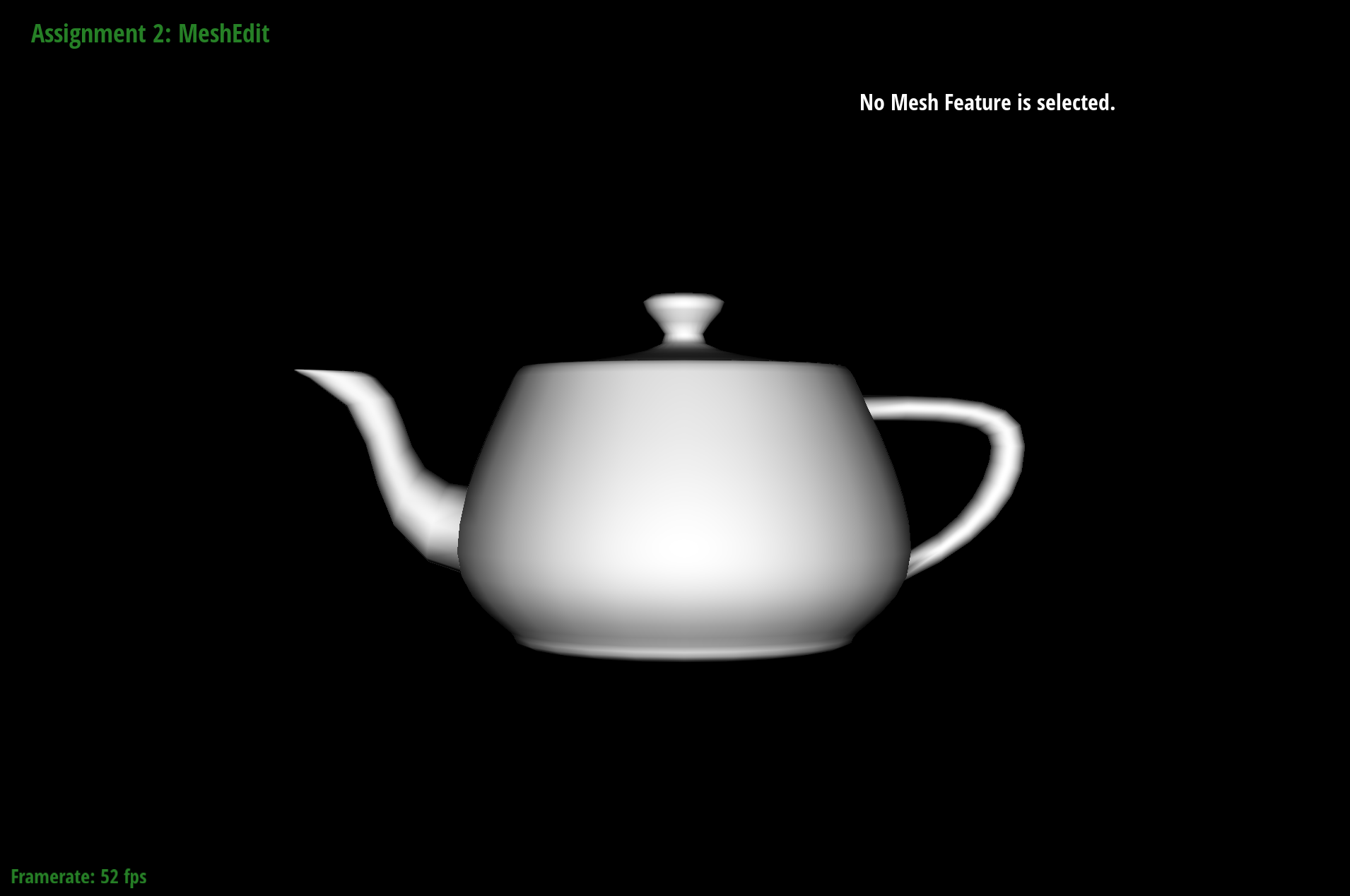
shaded rendered with smooth edges
Part 4: Half-edge flip
In this part of the project, I work on flipping edges. Below are visual representations of goals for this part of the project.
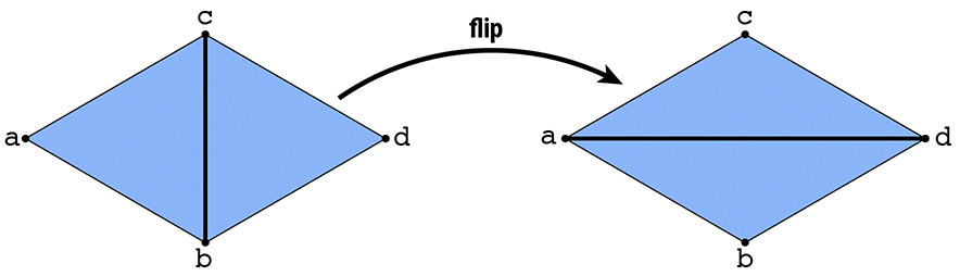
Visual representation of flip
In the top example, the 2 pairs of triangles are ABC and CBD. After the flips, the new triangles are ADC and ABD.
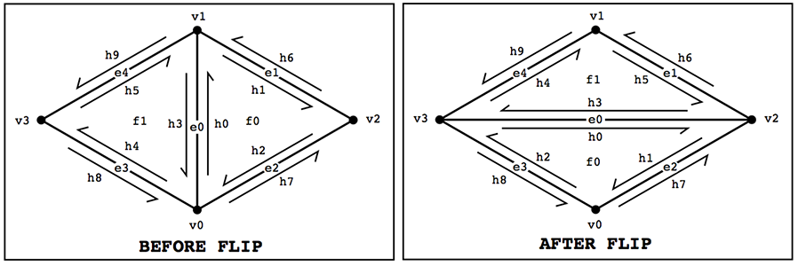
Diagram showing the changed edges/vertices/half-edges
Using the method of traversing through the triangles, I reassign the vertices, edges, and half-edges by pointing pointers to its modified element. In this process there was no need to recreate a new element. So first I save the current pointers and then reassign the elements to its modified element.
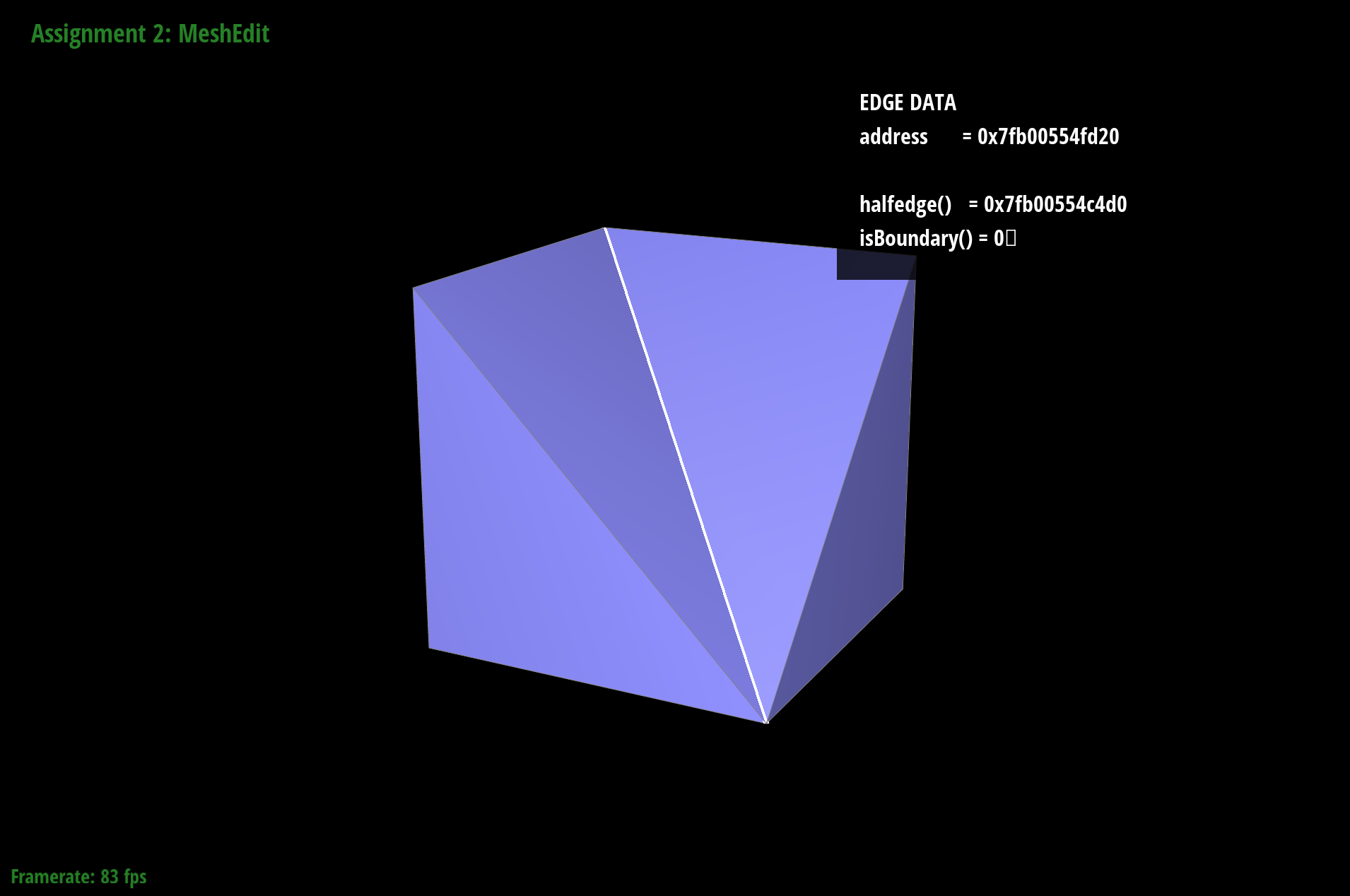
Below you can see the effect of the edge flipping. In the top photos you can see the flip of the edge. In the bottom photos, you can see the result of the edge flip and how it changed the look of the cube.
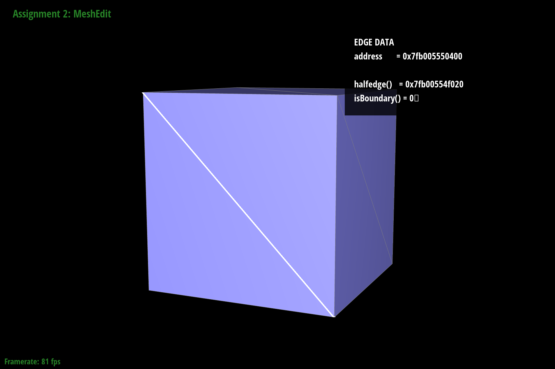
Original
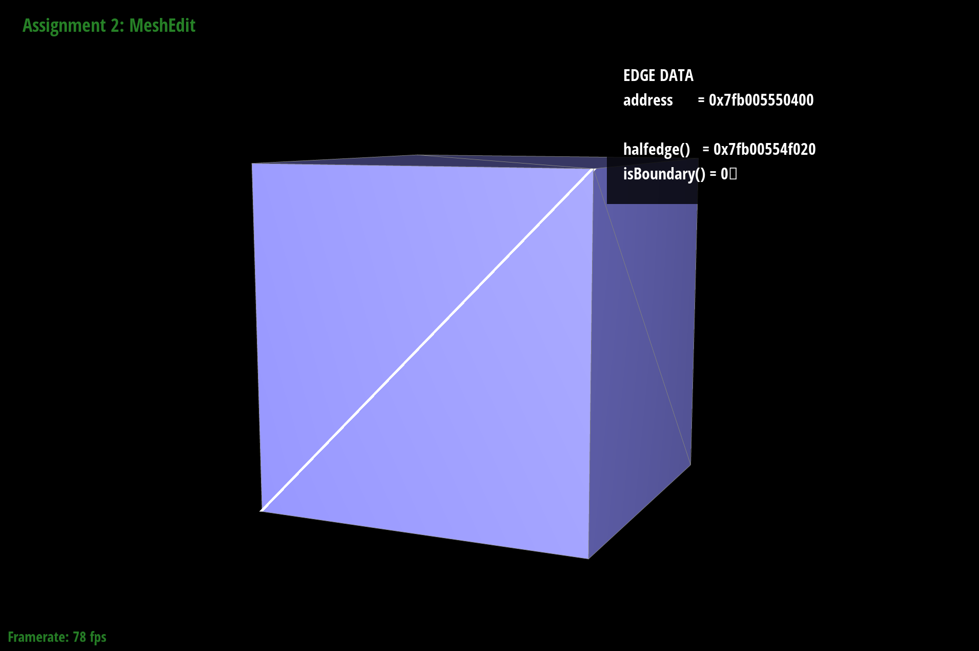
flipped edge
original 3D model
flipped edge original 3D model
Reassigning these elements could get ugly if you don’t keep track of what should be reassigned to what. Referring to the diagram above helped declutter the mess of knowing what needed to be reassigned. Another thing that helped was reassigning everything first just so I knew it worked and then later going back and deleting whatever we didn’t need.
Part 5: Half-edge split
In this part of the project, I work on splitting edges. Below is a visual representation of the goal for this part of the project.
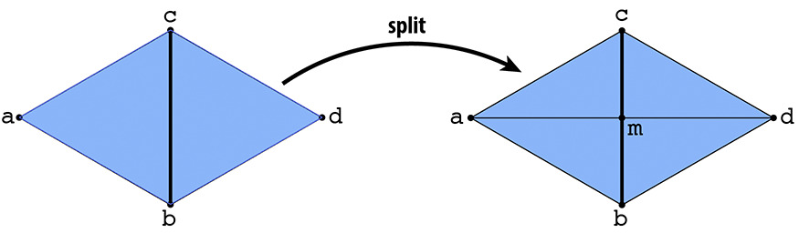
splitting diagram
In the top example, the 2 pairs of triangles are ABC and CBD with one edge BC. After the split, the new triangles are AMC, CDM, DMB, and ABM.
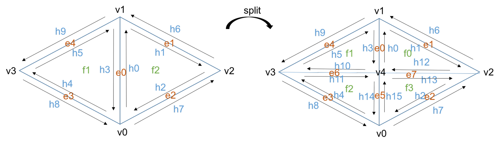
Image result for edge splitting diagram
Using the method of traversing through the triangles, I reassign the vertices, edges, and half-edges by pointing pointers to its modified element. Unlike flipping edges, we had to add a new vertex, 3 more edges, and 6 more half-edges. So first I save the current pointers, create the new elements, and then reassign the elements to its modified element.
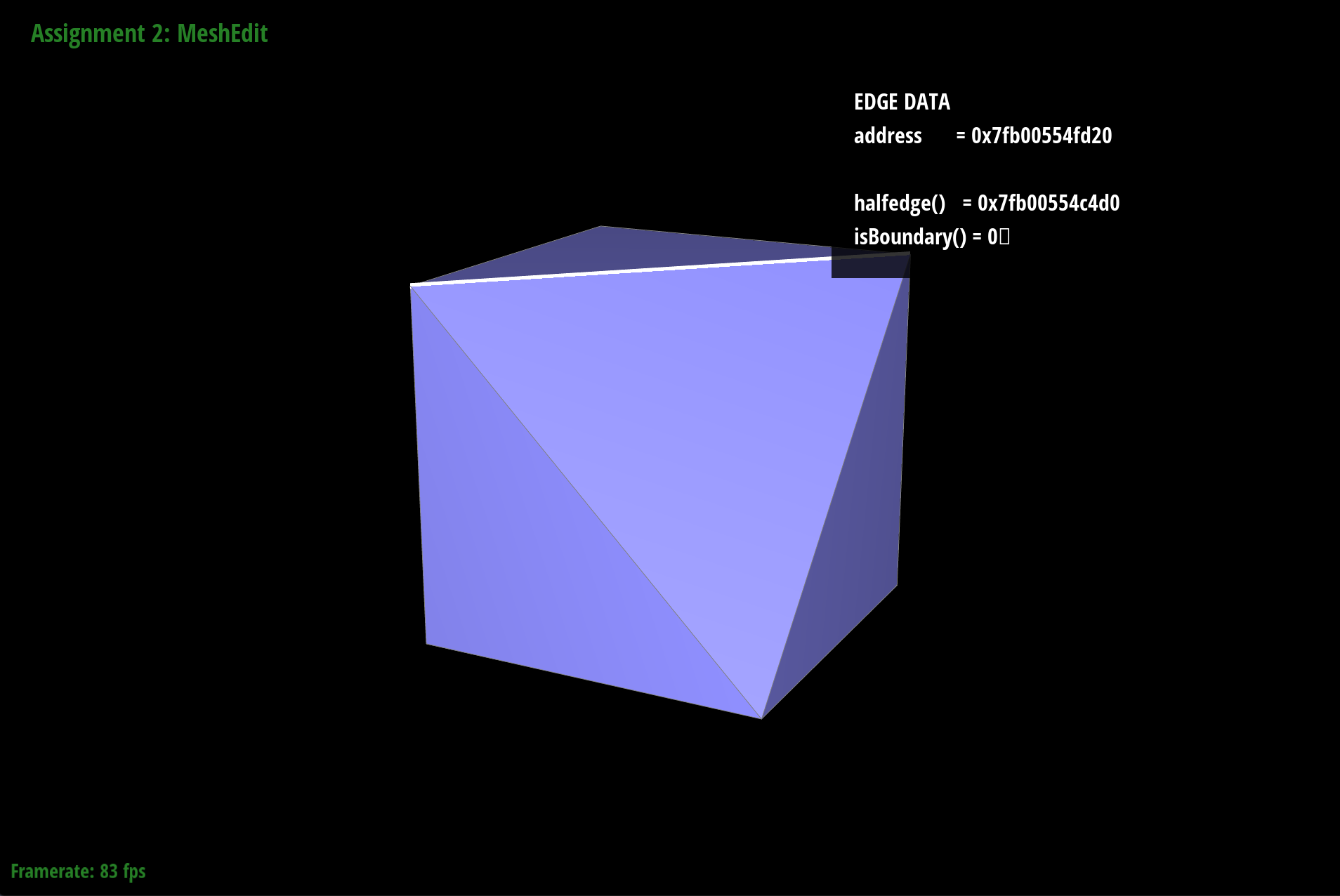
Below you can see the effect of the edge splitting. In the top left photo you see the original edge. In the top right edge, you see the effect of splitting the edge. It splits the edge and creates 3 more edges totaling in 4 faces. In the bottom photo you can see the result of the edge flipping and edge splitting and ultimately how it changes the look of the cube.
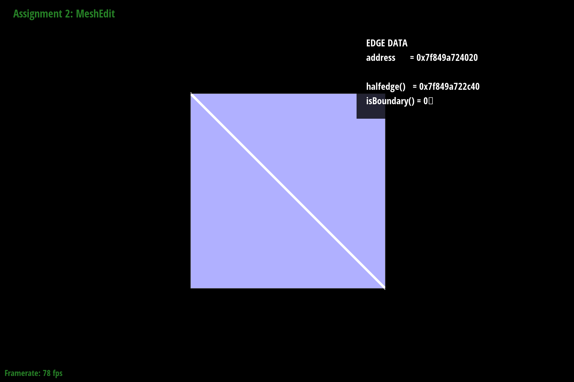
original edge
edge after split
flips and splitting
Part 6: Loop subdivision for mesh upsampling
In the process of loop sampling we want to take take a simple polygon with low resolution and loop subdivision using interpolation.
This process requires 2 steps:
- Split the triangle into four parts by connecting the midpoints as shown below
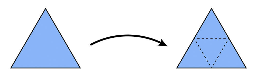
split to 4 parts
- Update the vertex position as a weighted average of the neighboring positions.
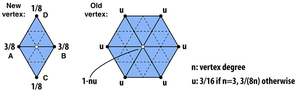
averaged vertex positions
As you recursively applying these steps, the object will become smoother and smoother.
Essentially what we are doing is splitting all the edges of the mesh and then flipping is the edge has a point on a new and old vertex. Below is an illustration of what that looks like.
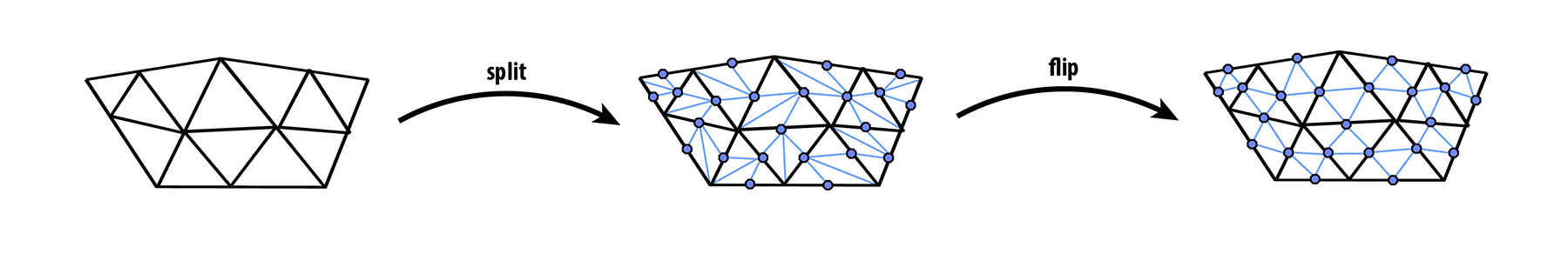
Visualization of subdivision
For implementing this idea:
- Loop through the vertices and mark them to false.
- Compute the sum of neighboring vertex positions and then compute the vertex’s new position and store them in Vertex::newPosition.
- Loop through all the edges and mark them as false
- Compute the new positions of the vertices that will be the midpoint of the edges and store them in Edge::newPosition
- Loop through all the isNew == false edges and split them if not a boundary edge. Then we mark the new vertex as isNew = true and the new edges as isNew = true. Finally set the new vertex to the new position of the edge split
- Loop through the edges and flip any new edge is it is connected to an old and new vertex.
- copy the Vertex::newPosition to Vertex::position
- Loop through every vertex and edge and set isNew = false
Below are some examples of loop subdivision that shows what the object looks like iteration by iteration.
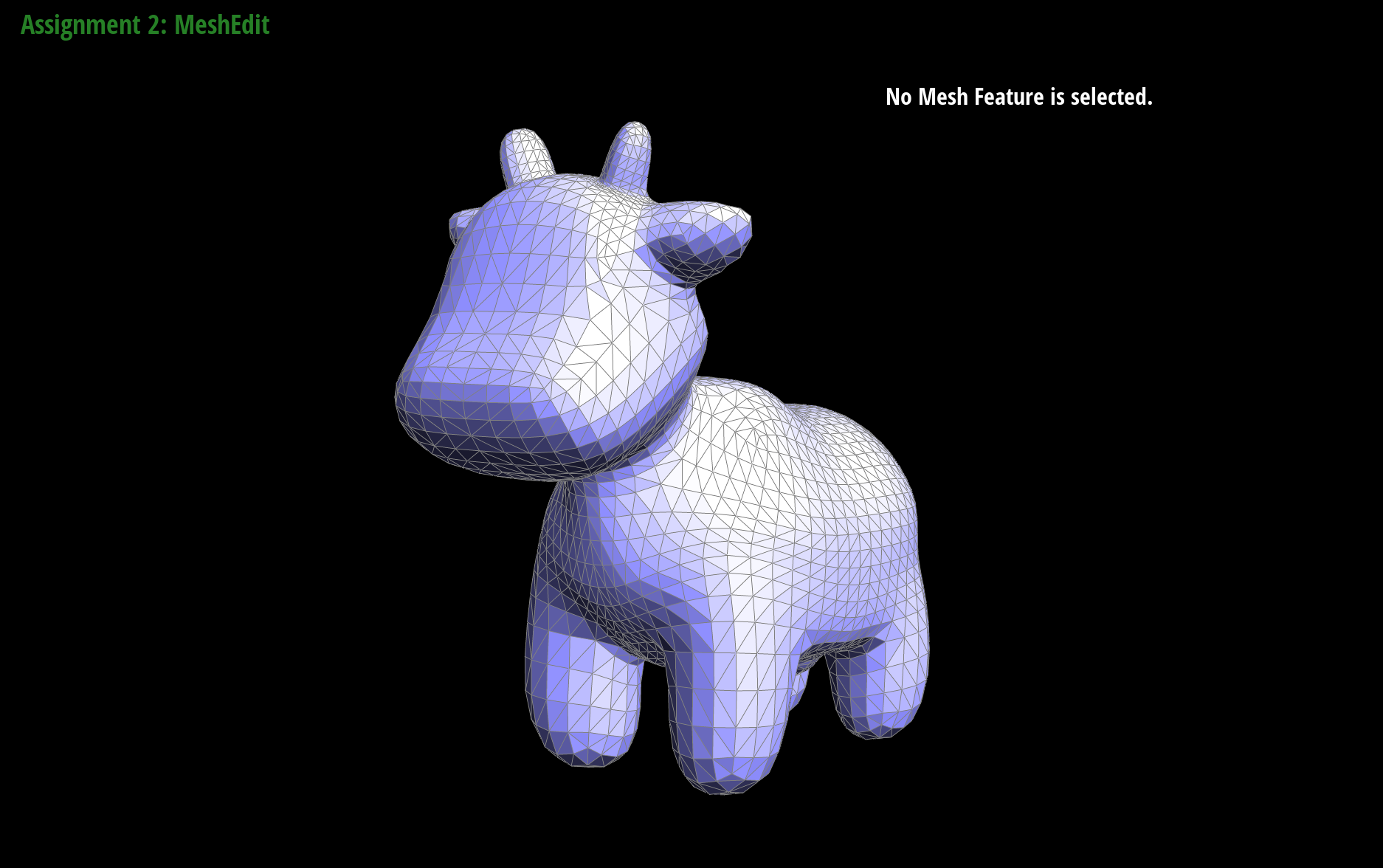
cow with no subdiving
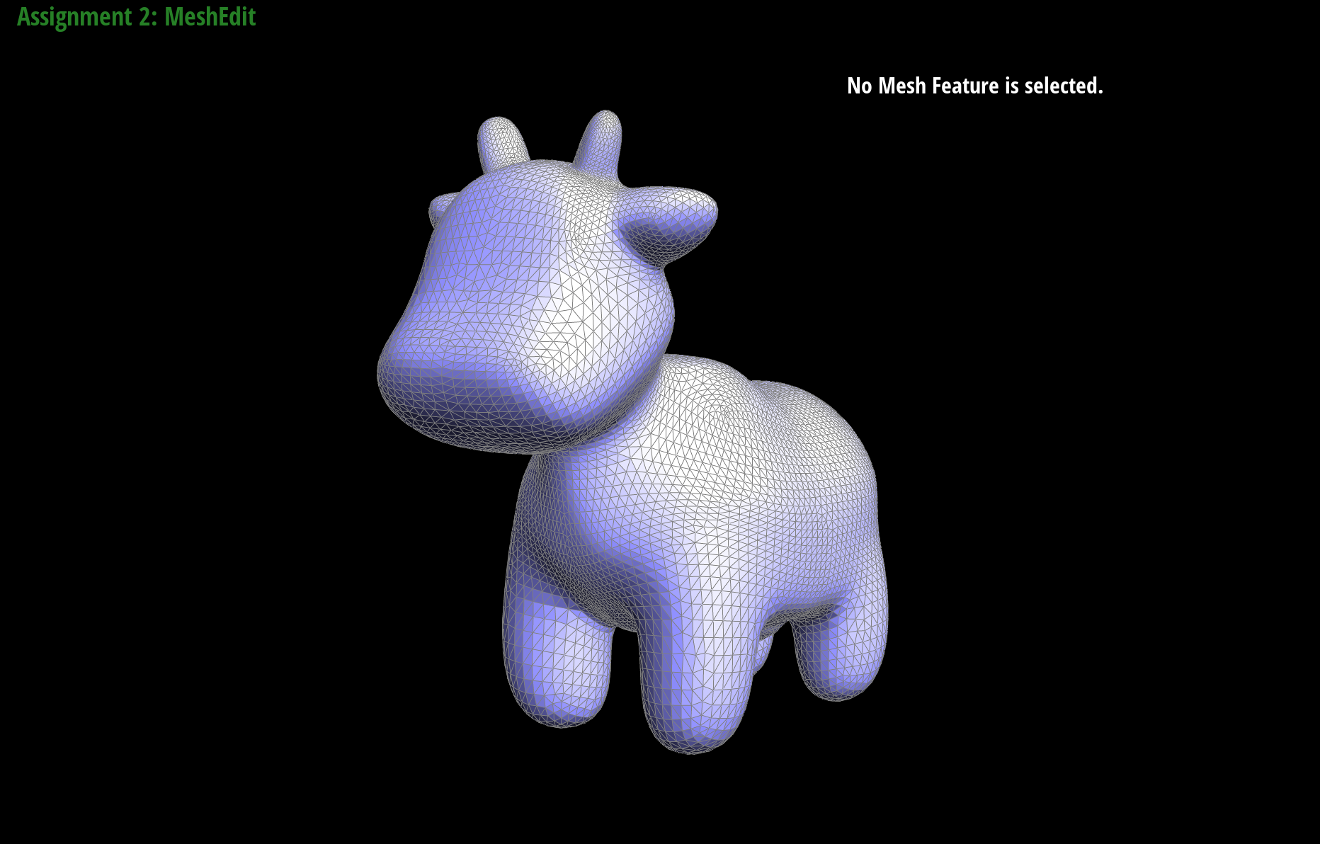
cow with subdiving
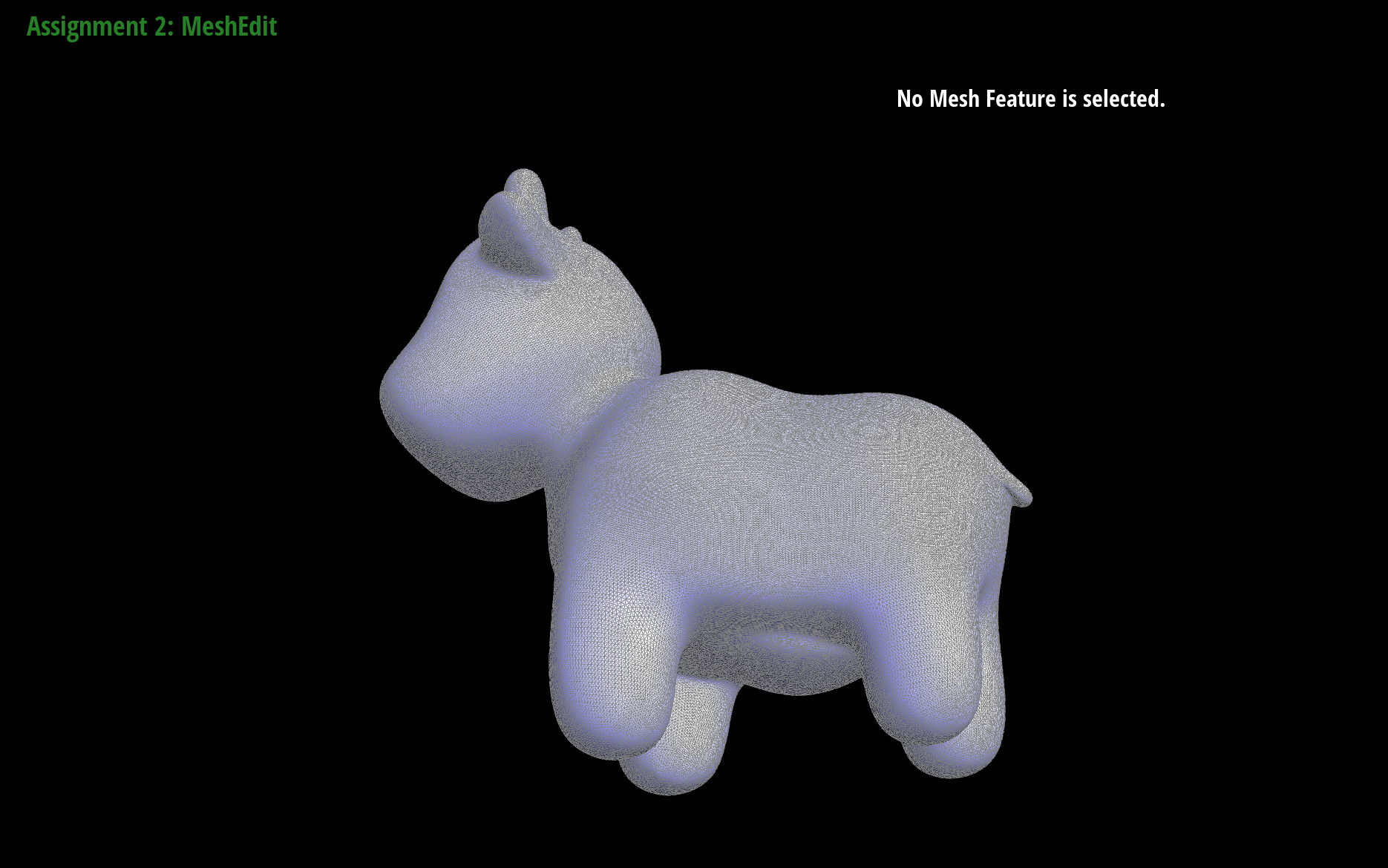
cow more subdividing
By the following example you can see how at each step each face is subdivided and each iteration looks smoother relative to its previous iteration.
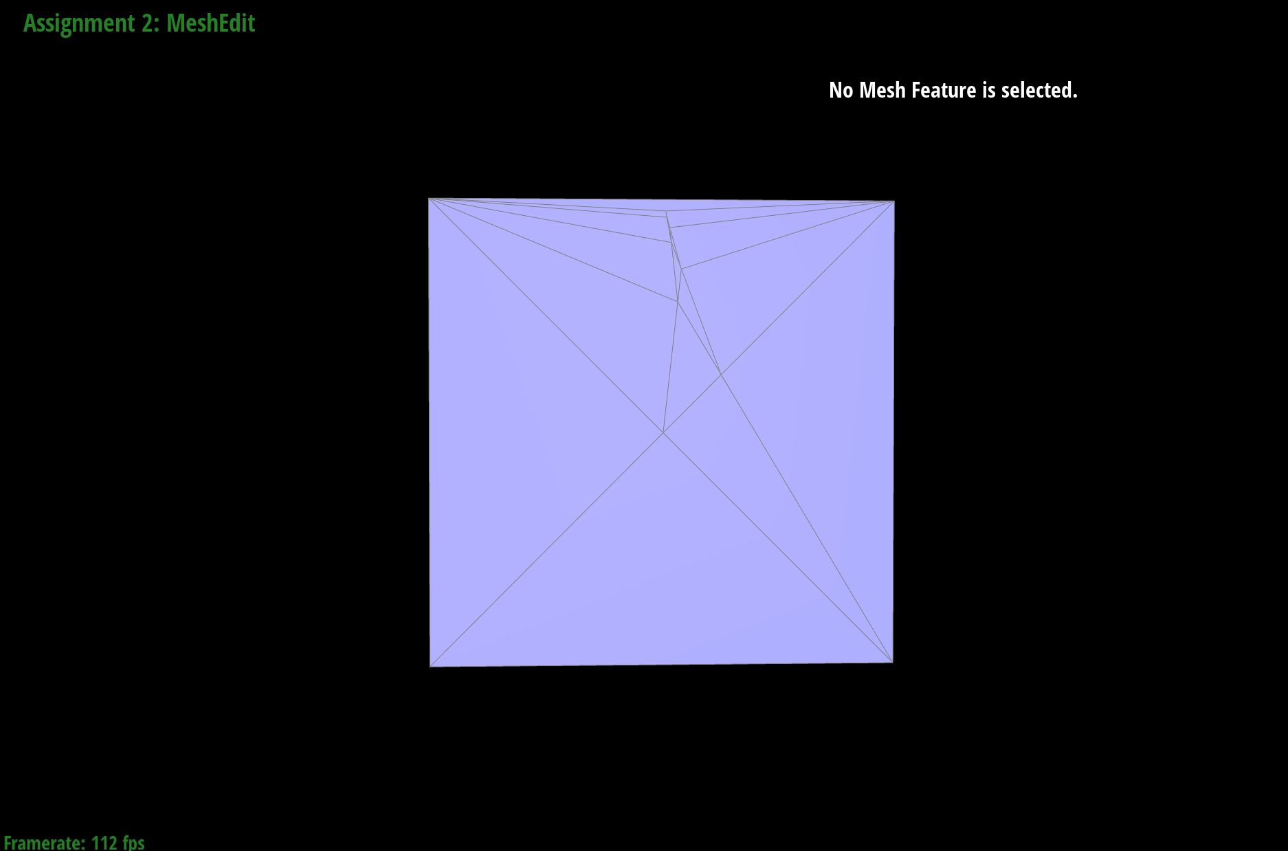
Below we smooth the edges of the cube but even when we iteratively subdivide we still get asymmetric sides.
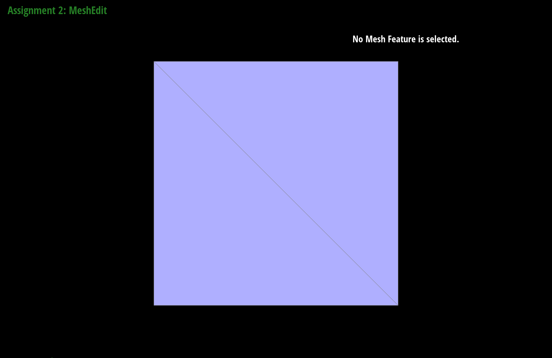
cube with no subdiving
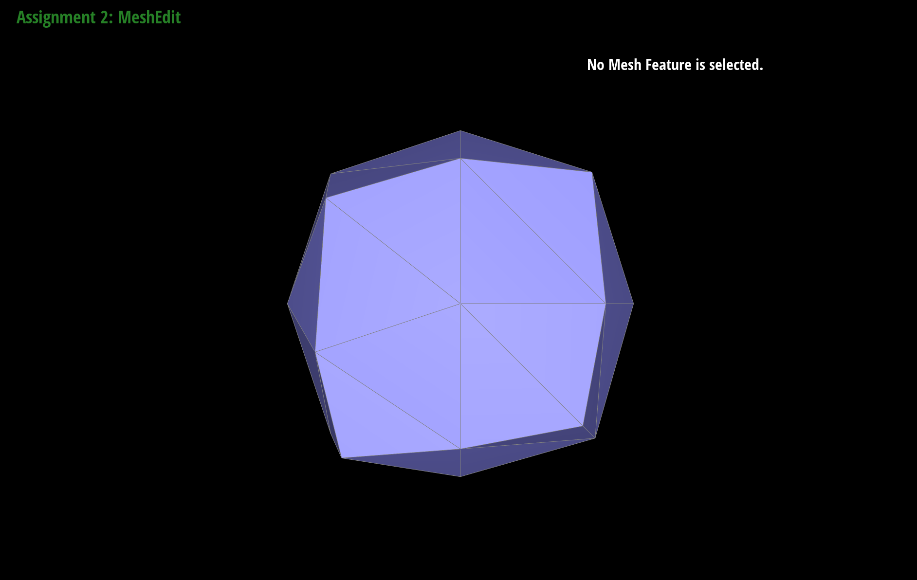
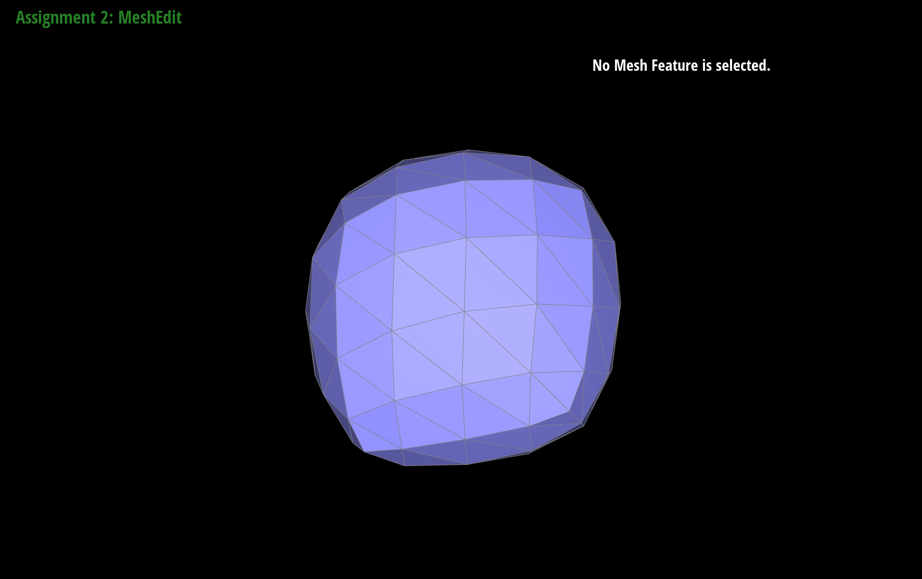
asymmetric
By pre-splitting the edges we can lessen the smoothing effect and create more sharper edges. Below you can see the effect of pre-splitting.
cube splitting
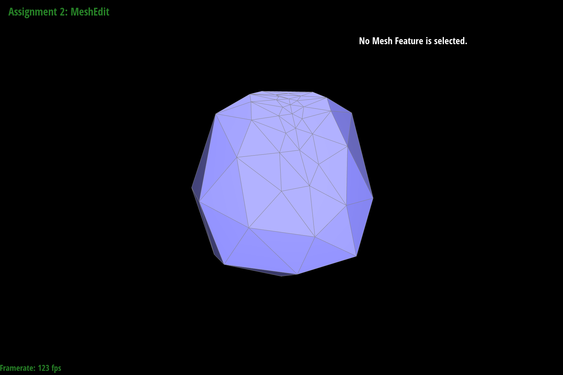
cube sharper edges
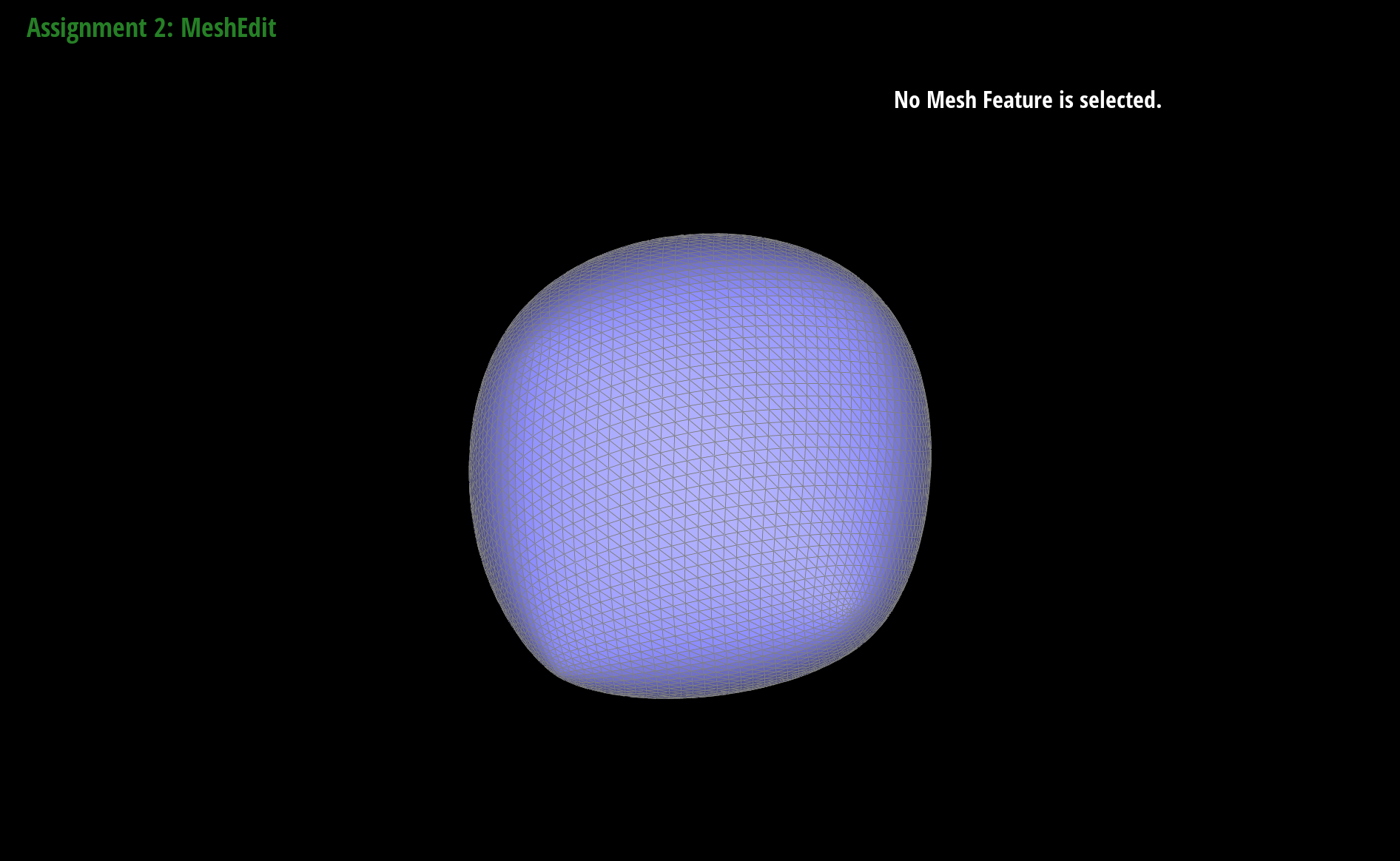
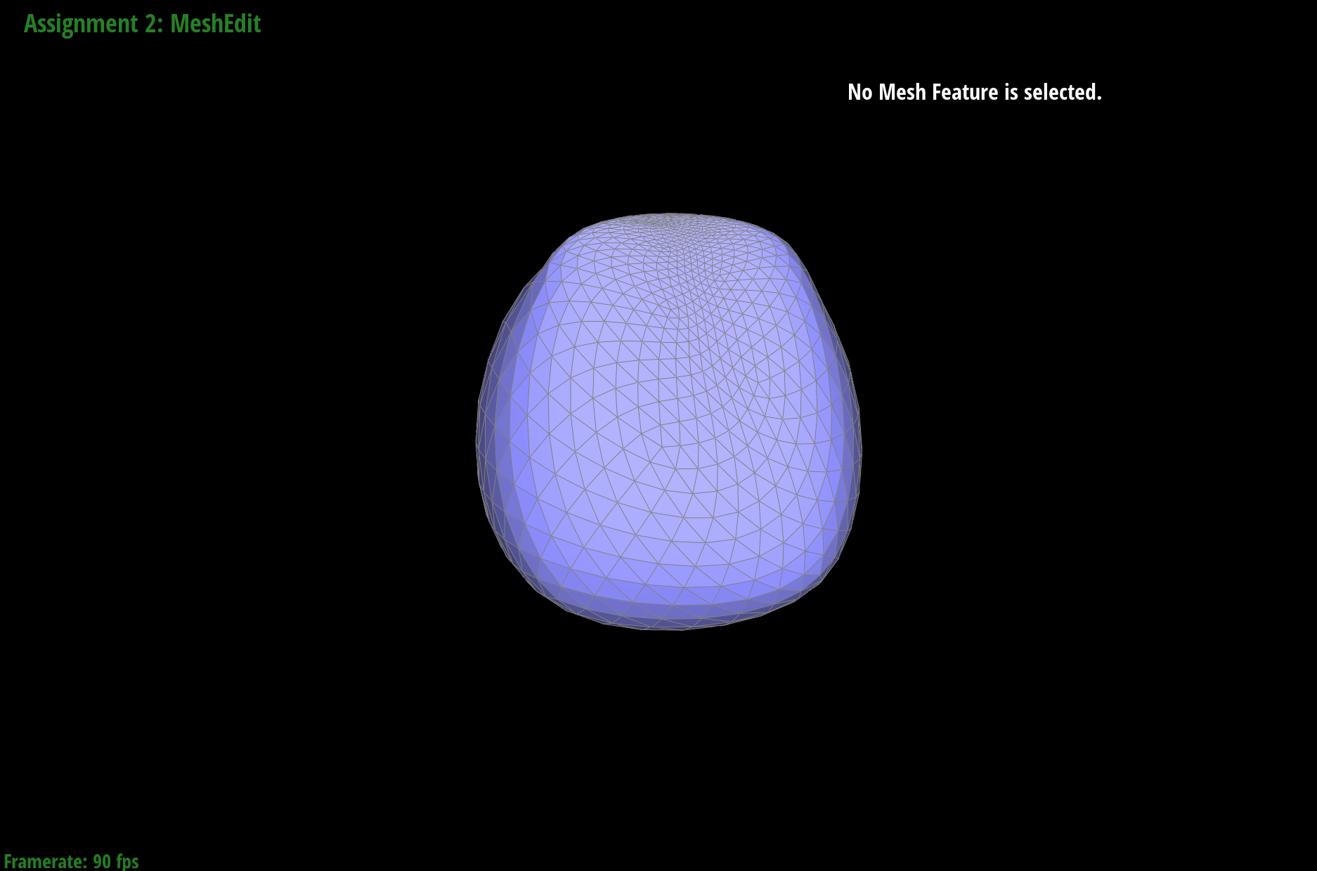
To lessen the asymmetric effect, we can pre-process the cube by flipping and splitting the mesh before upsampling. In the example below we can see that after loop subdivision the cube looks more symmetric.
cube with splitting
symmetric cube